Copyright 2016
Norfolk Southern Historical Society,
All Rights Reserved
 Link
to PDF Version
Link
to PDF VersionINTERSTATE COMMERCE COMMISSION
WASHINGTON
REPORT NO. 3763
NORFOLK SOUTHERN RAILWAY COMPANY IN RE ACCIDENT NEAR EDENTON, N. C., ON JULY 5, 1957
SUMMARY
Date: July 5, 1957
Railroad: Norfolk Southern
Location: Edenton, N. C.
Kind of accident: Derailment
Train involved: Freight
Train number: 64
Locomotive number: Diesel-electric units 1605 and 1610
Consist: 76 cars, caboose
Estimated speed: Less than 10 m. p. h.
Operation: Timetable and train orders
Track: Single; tangent; level
Weather: Clear
Time: 12:02 a.m.
Casualties: 2 killed; 3 injured
Cause: Failure of trestle
Recommendation: It is recommended that:
1. The Norfolk Southern Railway immediately arrange an inspection of the trestle by competent engineers to determine the present condition.
2. Any member of the structure disclosed to have deteriorated to such an extent that it can no longer be relied upon to perform its intended function, be replaced at once.
3. The carrier immediately initiate an adequate maintenance program and periodic inspection of the trestle.
INTERSTATE COMMERCE COMMISSION
REPORT NO. 3763
IN THE MATTER OF MAKING ACCIDENT INVESTIGATION REPORTS UNDER THE ACCIDENT REPORTS ACT OF MAY 6, 1910.
NORFOLK SOUTHERN RAILWAY COMPANY
September 25, 1957
Accident near Edenton, N. C., on July 5, 1957, caused by failure of a trestle.
REPORT OP THE COMMISSION 1
On July 5, 1957, there was a derailment of a freight train on the Norfolk Southern Railway, which resulted in the death of two train-service employees, and the injury of a road foreman of engines and two train-service employees.
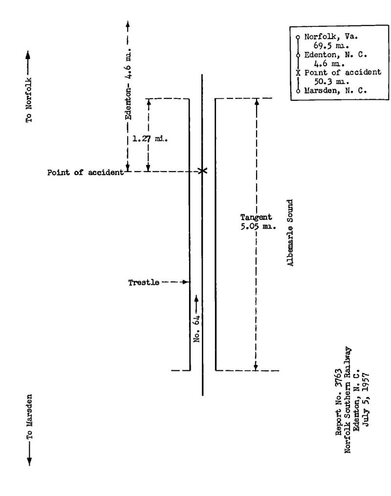
Report No. 3763 Norfolk Southern Railway Edenton, N. C. July 5, 1957
Location of Accident and Method of Operation
This accident occurred on that part of the Norfolk District extending between Marsden, N. C., and Norfolk, Va., 124.4 miles, a single-track line over which trains are operated by timetable and train orders. There is no block system in use. The accident occurred on the main track 4.6 miles south of Edenton and 1.27 miles south of the north end of a trestle which spans Albemarle Sound. The track on the trestle is tangent and the grade is level at the point of accident.
The maximum authorized speed in the vicinity of the point of accident is 10 miles per hour.
The open-deck trestle originally consisted of 2,131 untreated cypress and pine full-pile bents and was completed in 1910. It is 5.05 miles In length. Each bent consisted of four batter piles and to plumb piles having a diameter at the water line of from 12 inches to 14 inches, a 12-inch by 12-inch cap, two 3-inch by 10-inch diagonal sway braces, and two 3-inch by 12-inch horizontal sash braces. The batter of the outside batter piles was 3:12 and of the inner batter piles 1-1/2:12. The cap was secured to the top of each pile by a 3/4-inch drift bolt. At the cap, the center-lines of the piles were located, respectively, 1-1/2 feet, 3-1/2 feet, and 5-1/2 feet from the vertical center-line of the bent. The top ends and the bottom ends of the diagonal sway braces were secured to the ends of the cap and outside batter piles, respectively, by 3/4-inch bolts. These braces were secured to the other piles by 1/2-inch by 8-inch spikes. The bottom ends of these braces were located approximately at the low-tide water level. The sash braces were located beneath the sway braces and were secured to each pile by a 3/4-inch bolt.
The bents were 12 feet 6 inches apart and were connected by four 8-inch by 16-inch by 25-foot untreated fir stringers located on the tops of the caps. Two stringers were located on each side of the vertical center-line of the bent at right angles to the cap and with the 16-inch dimension in a vertical position. The two stringers were secured together by 3/4-inch bolts with spacers between and were secured to the cap of each bent by a 3/4-inch drift bolt extending vertically through the outside stringer. The joints of the stringers were staggered and were located at the caps. The inside faces of the inside stringers were located 1 foot 9-3/4 inches from the vertical center-lines of the bents. The 7-inch by 8-inch by 9-foot untreated white oak ties were placed on the stringers at a distance of 14 inches between center-lines. They were secured to the inside stringers by 1/2-inch by 12-inch spikes. The rails were single-spiked. No tie plates were provided. The tops of the rails were approximately 15-1/2 feet above the low-tide water level. Diagonal braces extending between bents in alternate bays were provided. These braces had a section of 3 inches by 12 inches and were secured by 3/4-inch drift bolts to the outside batter piles at the top ends and at the water level. A 3/4-inch bolt secured the braces on each side at the center. Untreated cypress and fir guard rails were provided and were secured to the ends of the ties by 5/8-inch spikes.
During the period extending from 1910 through 1949, inclusive, 8 bents were replaced with full-pile treated pine bents, and the plies of 2,093 bents were cut off approximately at the low-tide water level and untreated wood frames were applied. Each frame consists of a 12-inch by 12-inch base sill, two 12-inch by 12-inch batter posts having a batter of 3:12, two 12-inch by 12-inch plumb posts, a 12-inch by 12-inch cap, and two 3-inch by 10-inch diagonal sway braces. The sill is secured to each pile by a 3/4-inch drift bolt. Each post is secured to the sill by two 3/4-inch drift bolt. At the cap, the centers of the batter posts and the plump posts are, respectively, 4 feet 6 inches and 2 feet 6 inches from the vertical center-line of the bent. The tope ends and the bottom ends of the diagonal sway braces are secured to the ends of the cap and the ends of the sill, respectively, by 3/4-inch bolts. These braces are secured to the plump posts by 1/2-inch by 8-inch spikes. Diagonal braces extending between the frame-type bents are provided. These braces have a section of 3 inches by 10 Inches and are secured by 3/4-inch bolts to the batter posts at the top and bottom ends. A 3/4-inch bolt secures the braces on each side at the center. Two horizontal 4-inch by 12-Inch sash braces are provided at the top ends of the piles of a bent and two horizontal diagonal braces are provided between the sills of adjacent bents where considered necessary. No sway braces are provided between the water level and the mud line. On bents that have been reworked since 1955, the centers of the batter posts and the plumb posts are, respectively, 4 feet and 2 feet from the vertical center-line of the bent, and the sway braces are secured to the plumb posts by 3/4-inch bolts.
During the period extending between 1919 and 1923, inclusive, a third stringer was applied on each side of the trestle. The three stringers are secured together by eight 3/4-inch bolts with spacers between, and are secured to the cap of each bent by a 3/4-inch drift bolt extending vertically through the middle stringer. The joints of the stringers are staggered and are located at the caps. The center-lines of the middle stringers are located 2 feet 5-1/2 inches from the vertical center-line of the bent.
During 1949, a program of replacing bents with full-pile treated pine bents and wood stringers with fabricated steel stringers was initiated. Each of these bents consists of four batter piles and two plumb piles, a 12-inch by 12-inch cap, two 3-inch by 10-inch diagonal sway braces, and two 3-inch by 10-inch horizontal sash braces. All members of the bent are treated pine. The plies comply with the American Railway Engineering Association specifications for wood piles. The batter of the outside batter piles is 3:12 and of the inner batter plies 1-1/2:12. The cap is secured to the top of each pile by a 3/4-inch drift bolt. At the cap, the centerlines of the piles are located, respectively, 1 foot 1-1/2 Inches, 3 feet 3-1/2 inches, and 5 feet 6-1/2 inches from the vertical center-line of the bent. The diagonal sway braces are secured by 3/4-inch bolts to the ends of the caps and outside batter piles at the top ends and to the outside batter piles at the bottom ends. These braces are secured to the other plies by 3/4-inch bolts. The bottom ends of these braces are located approximately at the low-tide water level. The sash braces are located beneath the sway braces and are secured to each pile by a 3/4 -inch bolt. The fabricated steel stringers consist of two 16-inch by 7-inch WF 1-beam sections 25 feet in length weighing 45 pounds per foot. The 16-inch dimension is placed vertically. The sections are spaced 15 inches apart by 15-inch channels 8 inches in length bolted to the webs of the section. A steel plate 1/2 inch by 18 Inches is provided at each cap location. A 3-inch by 3-inch angle 22-1/2 inches In length is located on each side of the cap and secures the stringer from longitudinal movement. The plate and angles are bolted to the bottom flanges of the sections. A 7/8-inch lag screw secures the plate to the cap. Where steel stringers are applied, 8-inch by 8-inch by 9-foot treated ties are provided. Clip anchors securing ties to the flanges of the sections are provided at every fourth tie.
At the time of the accident 19 of the bents of the trestle contained original full piles, approximately 82 percent of the bents were of the frame type, and the other bents were of the full-pile treated pine type.
Description of Accident
No. 64, a south-bound second-class freight train consisted of diesel-electric units 1605 and 1610, coupled in multiple-unit control, 76 cars, and a caboose. This train departed from Marsden, the last open office, at 9:20 p.m., on July 4, 20 minutes late, and while moving over the trestle at a speed of less than 10 miles per hour, the trestle failed under the rear truck of the first diesel-electric unit and the front truck of the second diesel-electric unit. Both units and the first car feel through the trestle. The second car stopped with the front end extending over the damaged portion of the trestle. Both diesel-electric units and the first car were badly damaged. The third car was somewhat damaged.
The engineer and the conductor were killed. The fireman, a brakeman, and a road foreman of engines were injured.
The weather was clear at the time of the accident, which occurred about 12:02 a.m.
Diesel-electric units 1605 and 1610 are of the road-switcher type. Each unit is mounted on two 6-wheel trucks the wheelbase of each truck is 11 feet 6 inches. The distance between truck centers is 32 feet 3 inches. The specified total weight of each unit in working order is 289,900 pounds.
Discussion
As No. 64 was approaching the point where the accident occurred, the engineer and the fireman were in the control compartment of the first diesel-electric unit, and the conductor, the brakeman, and a road foreman of engines were in the control compartment of the second diesel-electric unit. The flagman was in the caboose. The control compartments were located at the south end of the first diesel-electric unit and at the north end of the second diesel-electric unit. The brakes of the train had been tested and had functioned properly when used en route. The fireman and the brakeman said the first that they became aware of anything being wrong was when they heard timbers breaking. The road foreman said that the second diesel-electric unit swayed considerably immediately before the accident occurred. The surviving members of the crew said that the trestle filled under the south end of the first diesel-electric unit and the north end of the second diesel-electric unit. They said that no brake application was made immediately before the accident occurred. They estimated that the speed of the train at the time of the accident was less than 10 miles per hour.
Examination of the equipment after the accident occurred disclosed no defects which could have caused or contributed to the cause of the accident. Examination of the control equipment of the first diesel-electric unit disclosed that the isolation switch was in off position, the throttle was in closed position, the automatic brake valve was in emergency position, and the independent brake valve was in full application position, indicating that the engineer took action to stop the train at the time the accident occurred. The tapes of the speed-recording devices of both diesel-electric units were water-soaked and, as a result, were damaged to the extent that the recorded speed of the train immediately before the accident occurred could not be determined.
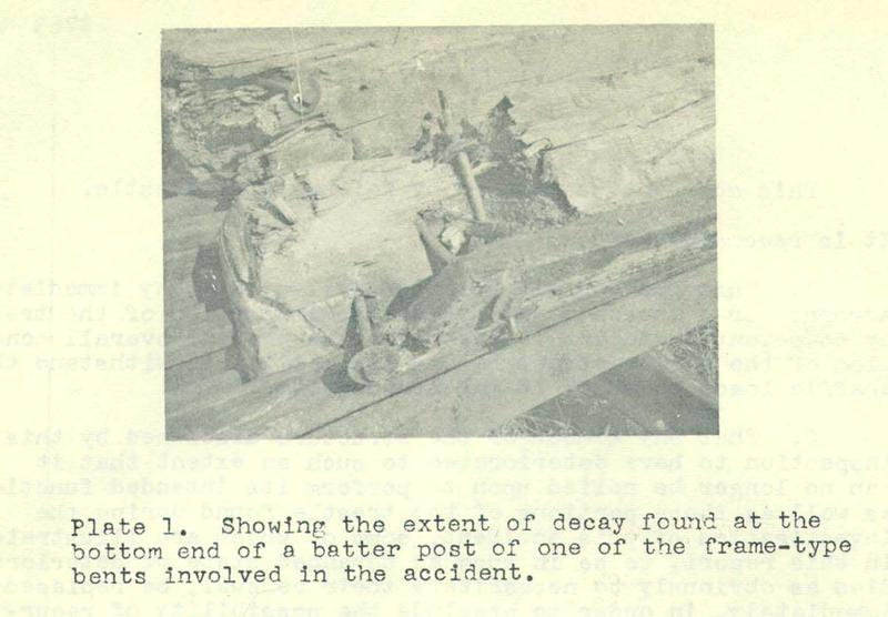
In the vicinity of the point of accident the trestle consisted of frame-type bents. The penetration of the plies was approximately 40 feet. At low tide the depth of the water is about 20 feet. The water level varies approximately 2 feet. There was no indication that equipment had been derailed before the trestle *** The frames of 11 bents were destroyed when the accident occurred. Twenty-one piles of these bents remained in place. Since only about 20 percent of the trestle members involved In the accident were recovered, the sequence of events that led to the failure of the trestle could not definitely be determined. There was no indication of damage to the plies by marine borers. One batter post of a frame involved in the accident was decayed near the bottom end to the extent that only approximately 30 percent of the original cross-sectional area was effective in bearing the load applied to the post. (See Plate 1.)
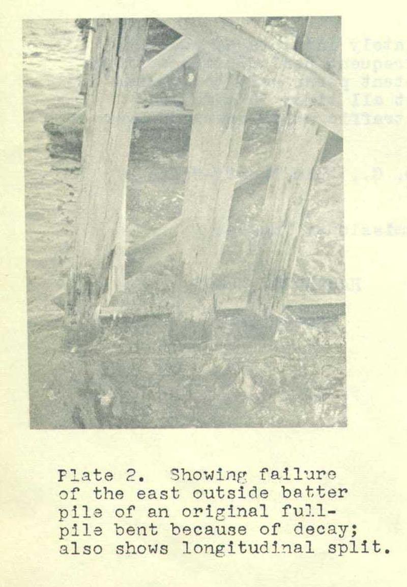
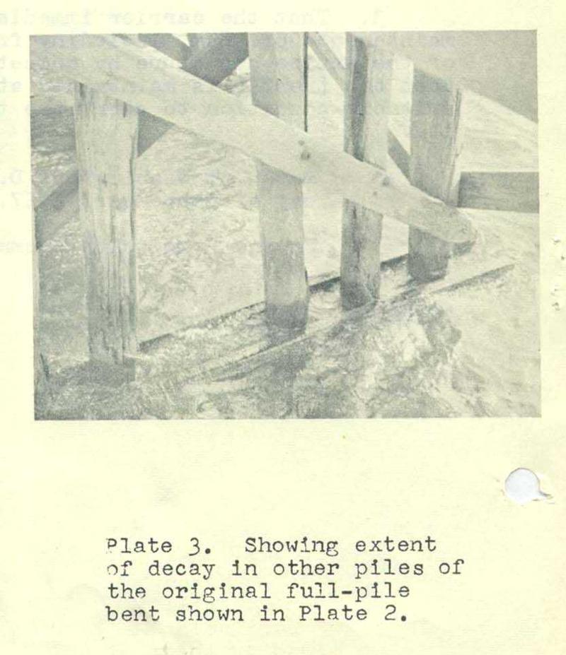
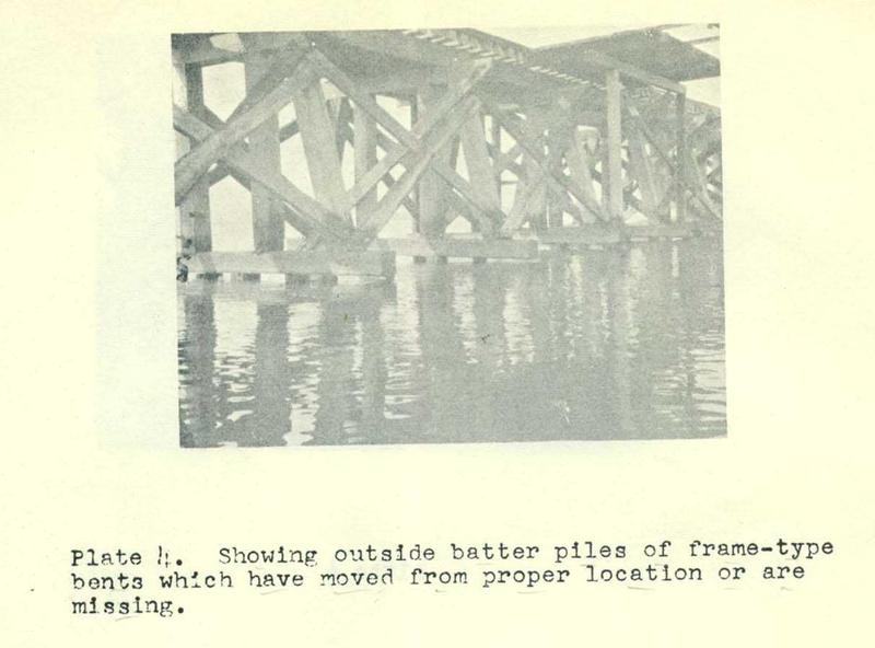
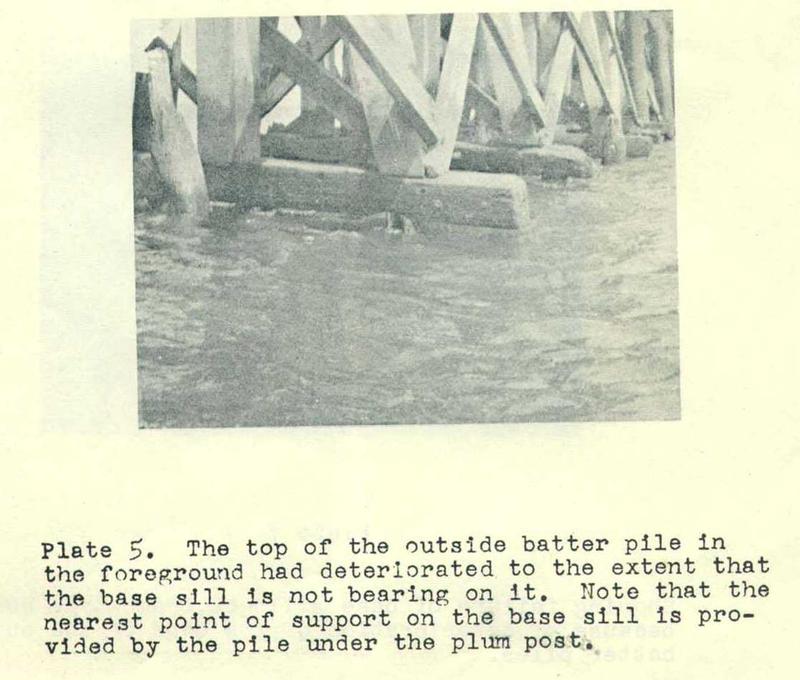
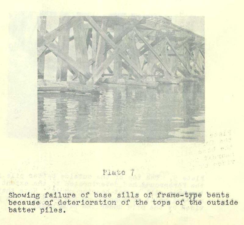
Examination of the remaining portion of the trestle from the deck after the accident occurred disclosed that a large number of ties were in various states of decay. None of the decayed ties were adjacent to each other. A number of stringers were decayed but not more than one decayed stringer was found in any group of three stringers on either side of the trestle. Examination from the water level disclosed that a number of piles-of the bents containing the original full piles were in various states of decay. The outside batter pile of one of these bents had spilt longitudinally and had decayed near the water line to the extant that it had failed. Two other piles In this bent were considerably decayed. (See Plate 2 and 3.) The tops of the plies supporting the frames of a considerable number of frame-type bents had deteriorated" to the extent that the sills were not bearing on them. Some of these bends had as many as three piles in that condition with results that the sill was subjected to high bending stresses and three piles were bearing a load which should have been distributed over six piles. A considerable number of frame-type bents were found in which the sill was not bearing on the outside batter pile. In some cases the pile was missing or had moved from its proper location, and in other cases the pile was in its proper location but the top of the pile had deteriorated to the extent that it was not in contact with the sill. (See Plates 4 and 5.) Under that condition the unsupported end of the sill was required to withstand the force transmitted by the batter post and high bending stresses were produced in the sill where it was supported by the inside better post. Two bents were found in which the sills had failed because the top of the outside batter pile was not in contact with the sill. (See Plates 6 and 7.) In each case the outside batter pile was in its proper location and prevented the sill from breaking off completely. It is probably in each of these cases that if the outside batter pile had moved from ts proper location or had been missing the bend would have failed.
The trestle is maintained by two regularly assigned bridge crews. Each crew inspects a portion of the trestle each working day. Bridge patrolmen inspect the trestle from a velocipede car after each train movement. Weekly inspection are made from the deck by a bridge supervisor who is frequently accompanied by an assistant chief engineer. These inspections are made by riding trains and track motor-cars, and by walking on the deck of the trestle. Inspections from the water level are made by boat. The last inspection made from the deck before the accident occurred was on July 3, 1957. No inspection had been made by boat since January 1957.
During the period extending between 1949 and 1956, inclusive, 274 original full-pile and frame-type bents were replaced with full-pile treated pine bents, and steel stringers having a total length of approximately 5,800 feet were applied. At the time of the accident the carrier's replacement program for 1957 indicated that 93 bents were to be replaced and that steel stringers having a total length of 400 feet were to be applied during that year. If the 1957 rate of replacement of bents is maintained in the future, it would require 19 years for the replacement of all original full-pile and frame-type bents.
Although this Commission has no jurisdiction over the maintenance and repair of bridges or trestles, our investigation discloses that through lack of maintenance the piling of this trestle is deteriorated to a dangerous degree. Cause
This accident was caused by failure of a trestle.
It is recommended:
1. That the Norfolk Southern Railway Company immediately arrange for a thorough and systematic inspection of the trestle by competent engineers to determine the present overall condition of the entire structure and Its ability to withstand the traffic loads to which it may be subjected.
2. That any member of the structure disclosed by this inspection to have deteriorated to such an extent that it can no longer be relied upon to perform its intended function, as well as those portions of the trestle found during the investigation of this accident, some of which are Illustrated in this report, to be in such an advanced state of deterioration as obviously to necessitate their renewal, be replaced immediately, in order to preclude the possibility of recurrence of the type of failure that resulted in collapse of the structure.
3. That the carrier immediately initiate an adequate maintenance program, including frequent periodic inspections of the entire structure by competent personnel, to insure that the trestle is maintained at all times in safe and suitable condition to carry the traffic which operates over it.
Dated at Washington, D. C., this twenty-fifth day or September, 1957.
By the Commission, Commissioner Tuggle.
(SEAL) HAROLD D. McCOY,
Secretary.
Plate 1. Showing the extent of decay found at the bottom end of a better post of one of the frame-type bents involved in the accident.
Plate 2. Showing failure of the east outside batter pile of an original full-pile bent because of decay; also shown longitudinal split.
Plate 3. Showing extent of decay in other piles of the original full-pile bent shown in Plate 2.
Plate 4. Showing outside batter piles of frame-type bents which have moved from proper location or are missing.
Plate 5. The top of the outside batter pile in the foreground had deteriorated to the extent that the base sill is not bearing on it. Note that the nearest point of support on the base sill is provided by the pile under the plum post.
Plate 6
Plate 7 Showing failure of base sills of frame-type bents because of deterioration of the tops of the outside batter piles.
FOOT NOTE
1. Under authority of section 17 (2) of the Interstate Commerce Act the above-entitled proceeding was referred by the Commission to Commissioner Tuggle for consideration and disposition. |